Feb 18, 2023
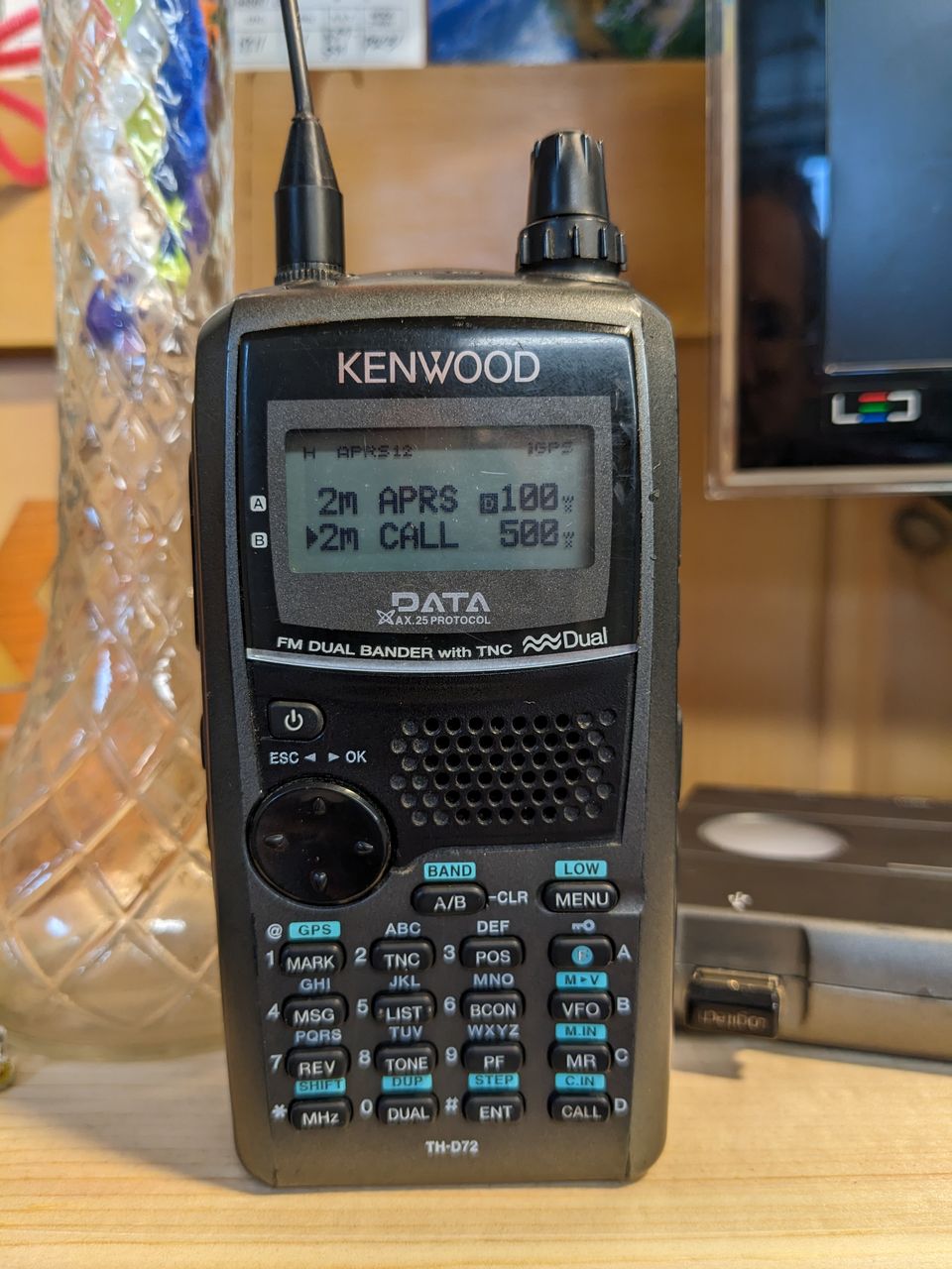
I broke the SMA antenna connector on my Kenwood TH-D72A radio recently, and I was surprised to find how easy it was to repair.
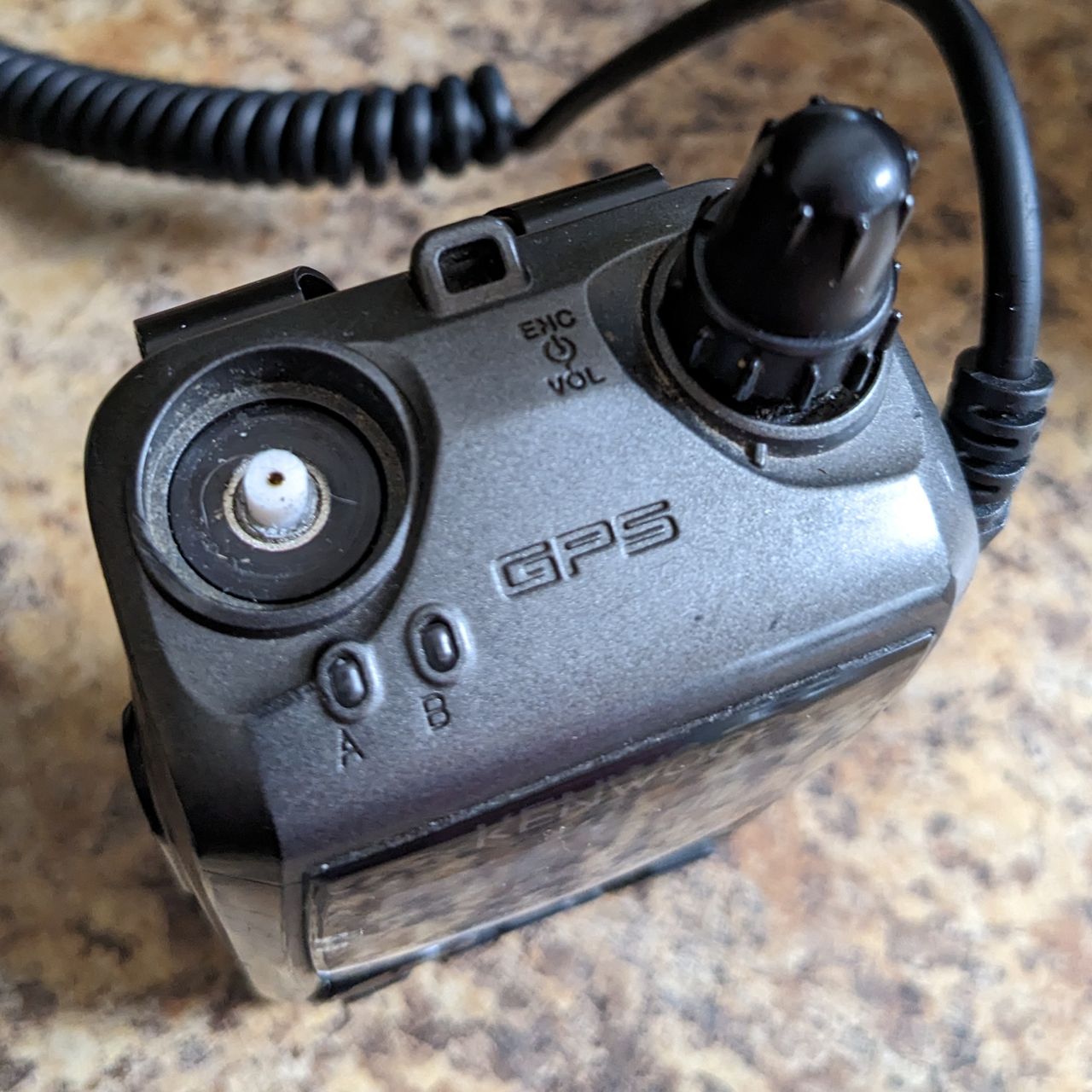
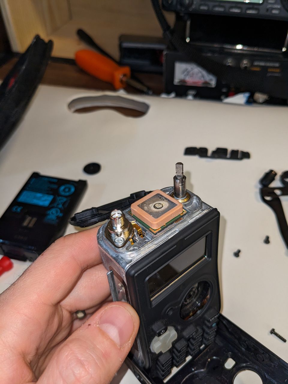
Broken
This happens to every handheld radio eventually, right? At least if you are a klutz like me. I dropped it in the garage, appeared undamaged, and then took it skiing with me. I'm not sure which started to break the connector, but when I got home it was fully broken off.
I was worried I would have to ship this off to the official service shop to get a new connector soldered on. At least, that's what I had to do after my first HT fell off my desk while still connected via a pigtail to an amplifier. Thankfully I feel a lot more confident pulling things apart and getting them back together now, and even doing a little soldering, so I thought I would see how bad of a repair this was. Turns out that the antenna is connected to the main board via a little spring, and the part was easy to find online and not too expensive.
So I ordered the part, was working on moving my hamshack and bringing my soldering station inside from the cold garage, and then life happened and it sat around in my desk drawer for about a month. I promised a few folks to document this, so here it goes.
I'm not a video producer person - I tried when iMovie first came out, but I learn better from written articles, but I will include lots of photos. If you want to find a video of someone tearing down a TH-D72A and repairing the speaker, here is the one that inspired me to try opening up the radio.
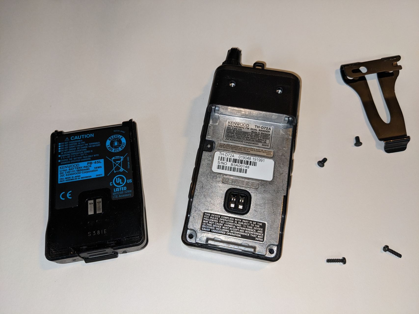
Disassembly
Pulling apart the radio is fairly easy. Remembering how to remove the battery (lift latch and then press button) was the most difficult part. There are two screws holding the belt clip on, and two screws at the bottom of the battery compartment that need to be removed.
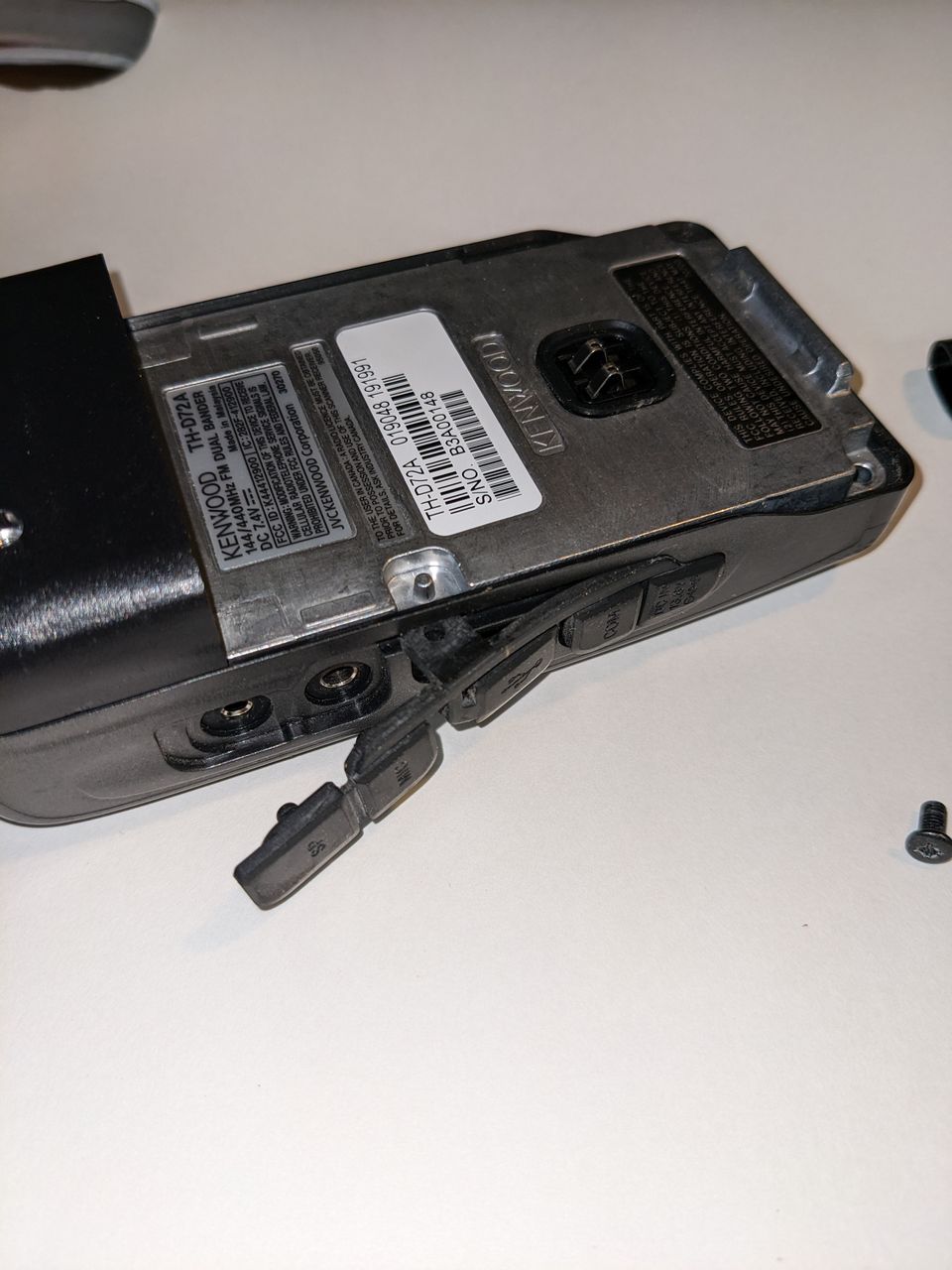
Next the rubber port cover needs to be removed. Slipping a small screwdriver under the nub that sticks into the battery compartment is necessary and then it comes off very easily.
Pulling off the cover takes a little muscle but should come off easily. At this point the button pad and arrow pad on the front are loose, nothing else holds them down. Be sure to put the arrow pad back on before reassembly! I forgot the first time. When you put them back together, trying to get the buttons to line up is important, but if a few are askew you can rub them around to get them back into place.
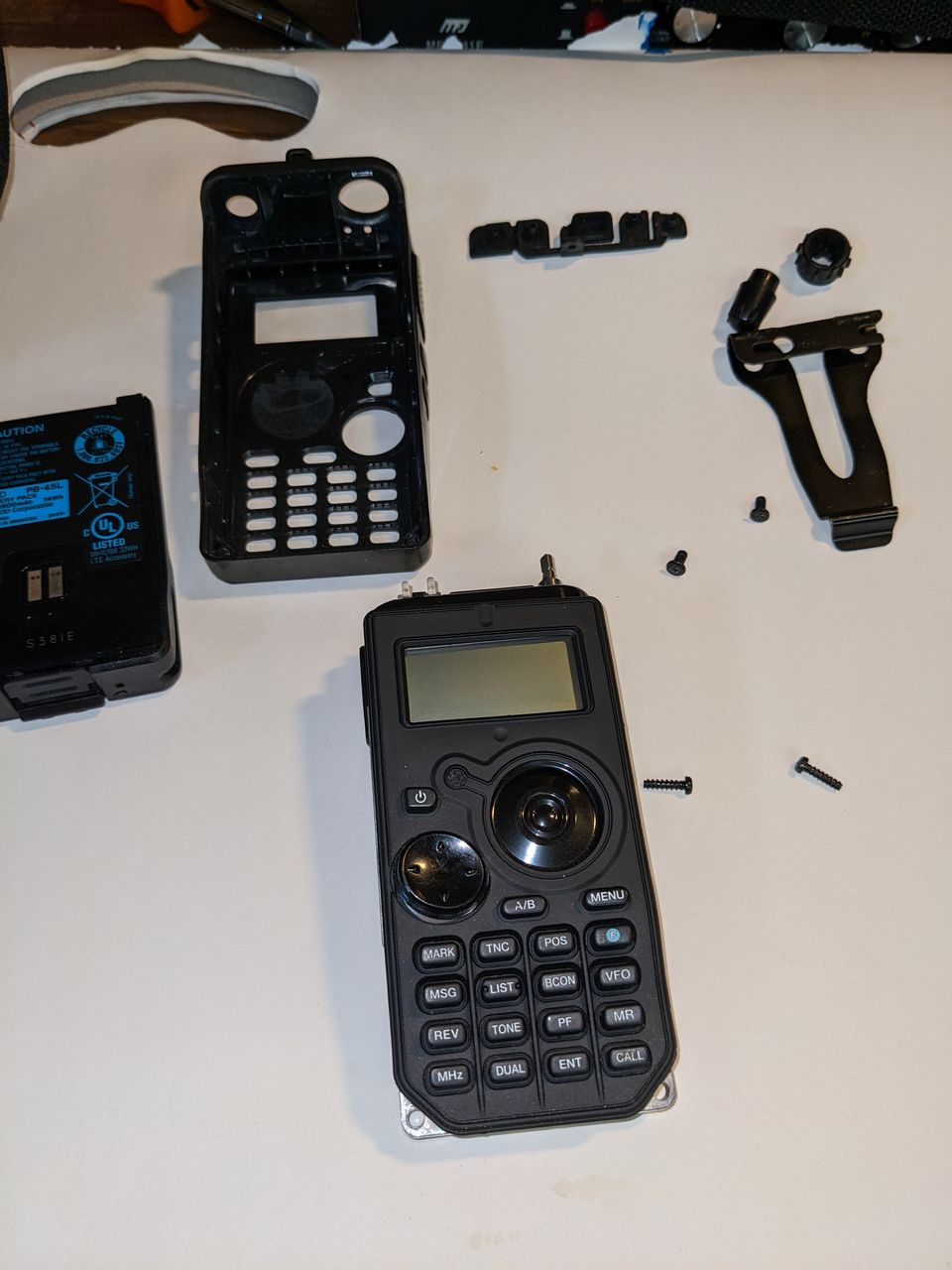
The two knobs for the dial and volume control need to be pulled off - these are just held in place by friction.
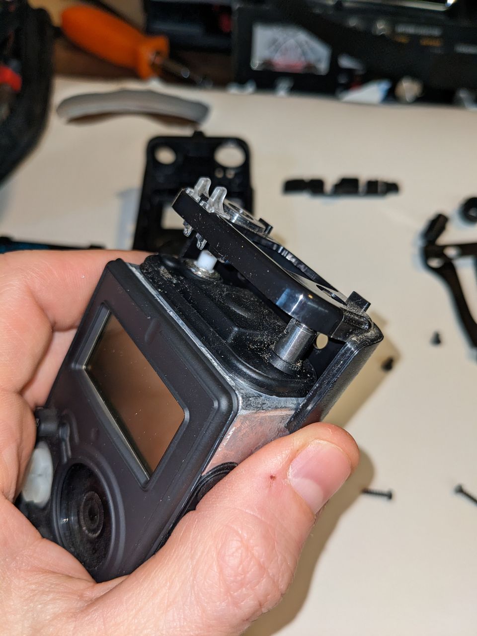
Finally you need to remove two covers over the top of the radio, this plastic one and a rubber one under it. The plastic one has a couple of points that snap it in place. Work around it to find these and slide it off. The rubber one can be bent back while working on the components under it. This plastic one is easy to forget and needs to go back on the radio before putting the cover back in place.
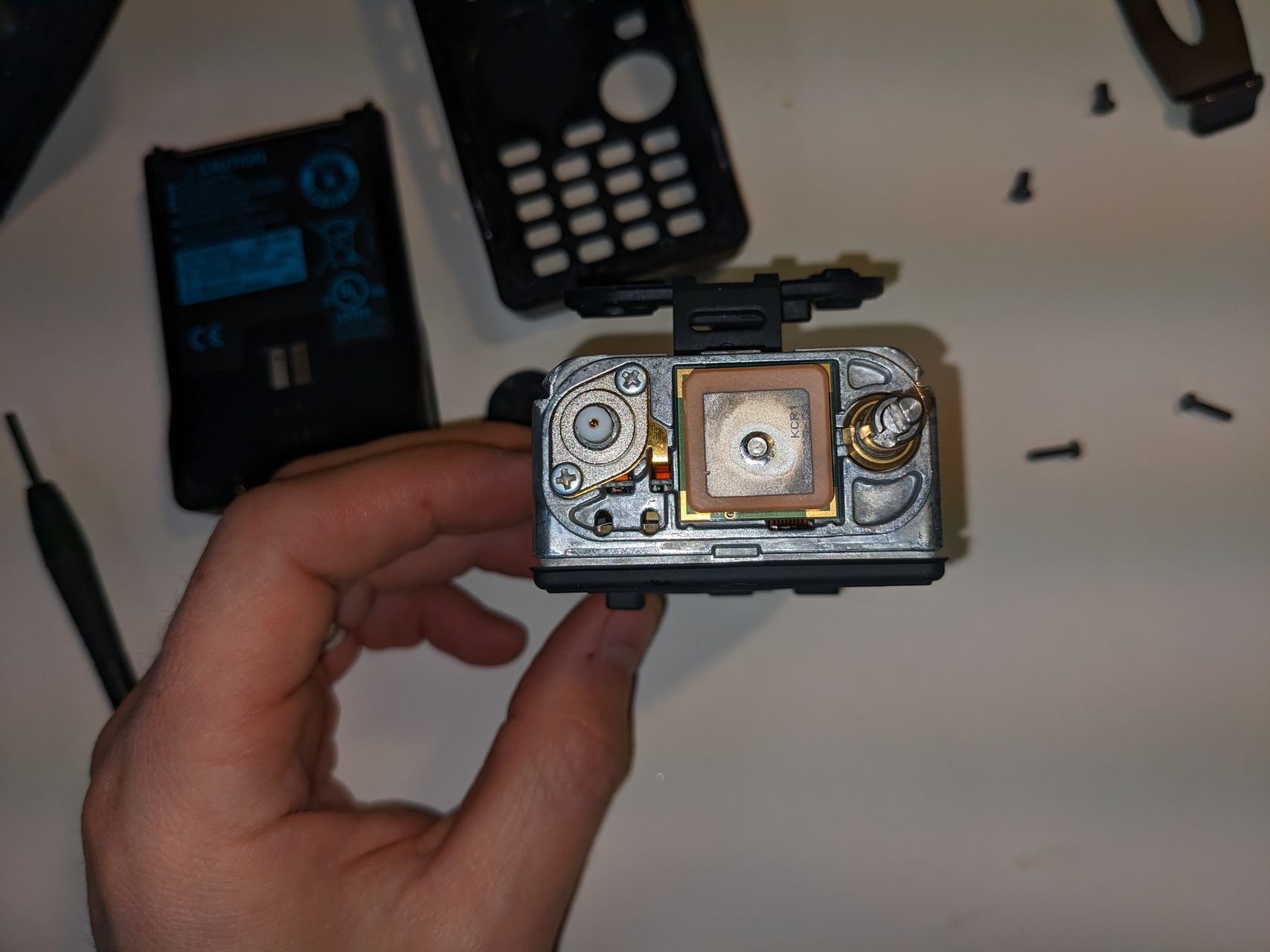
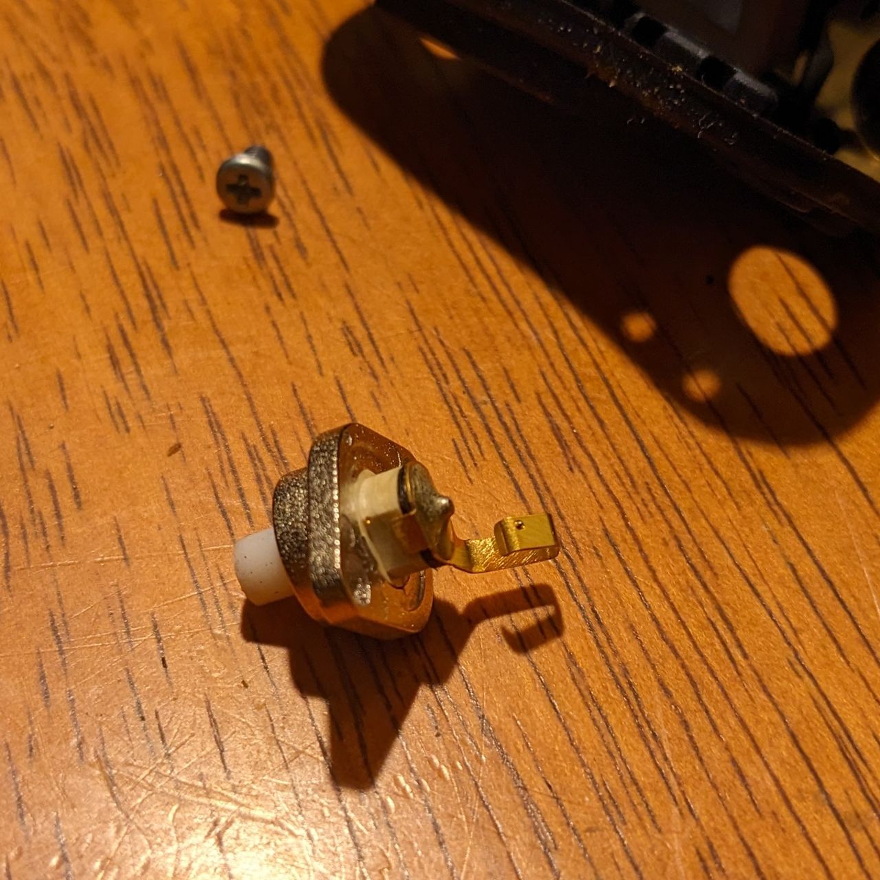
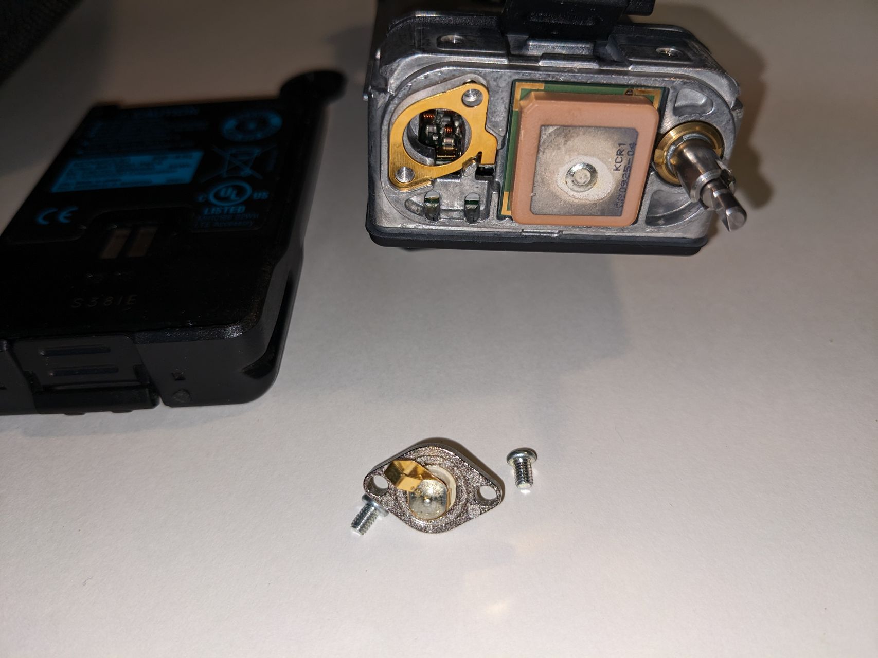
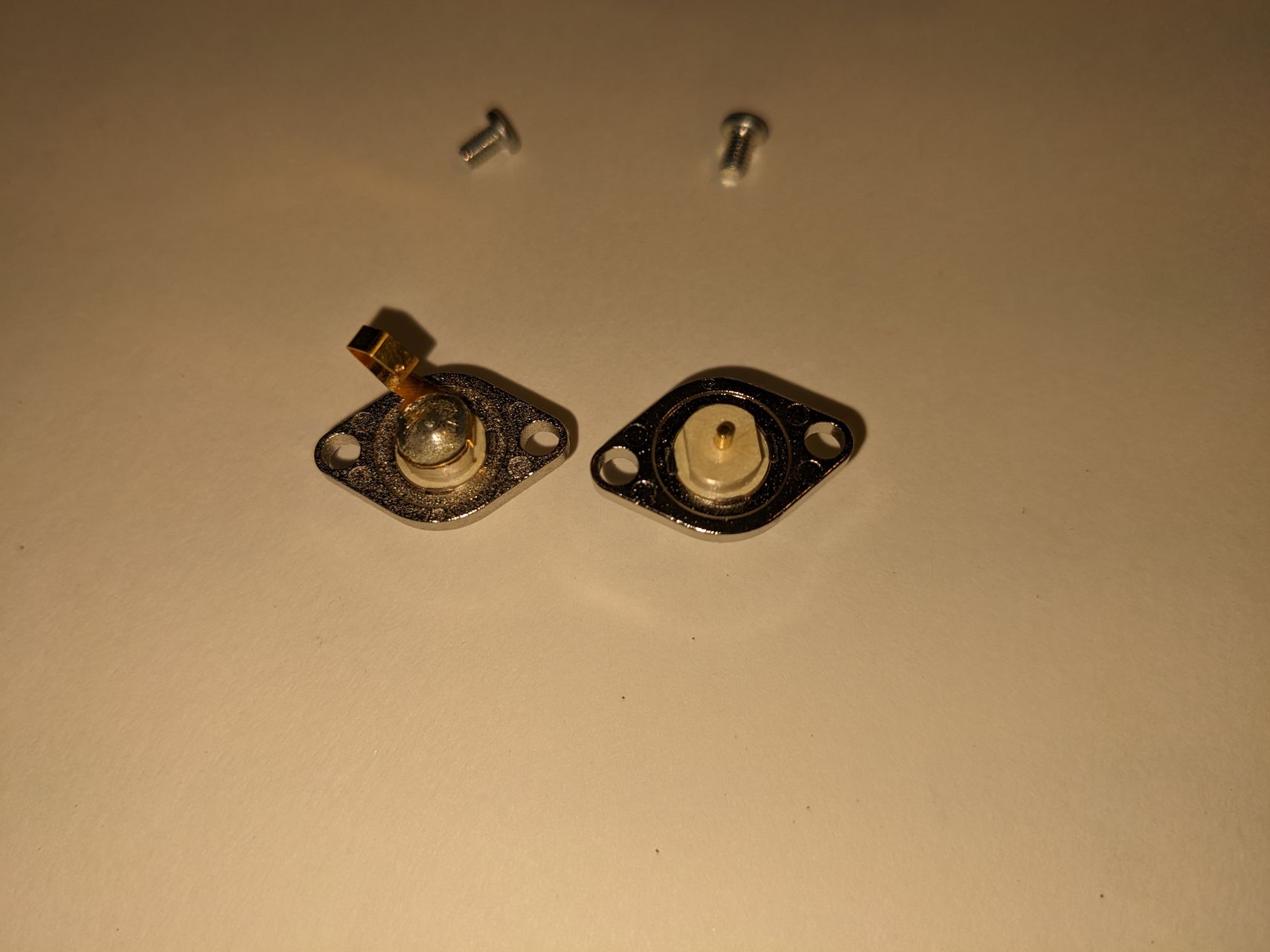
The connector is held into place with two small screws.
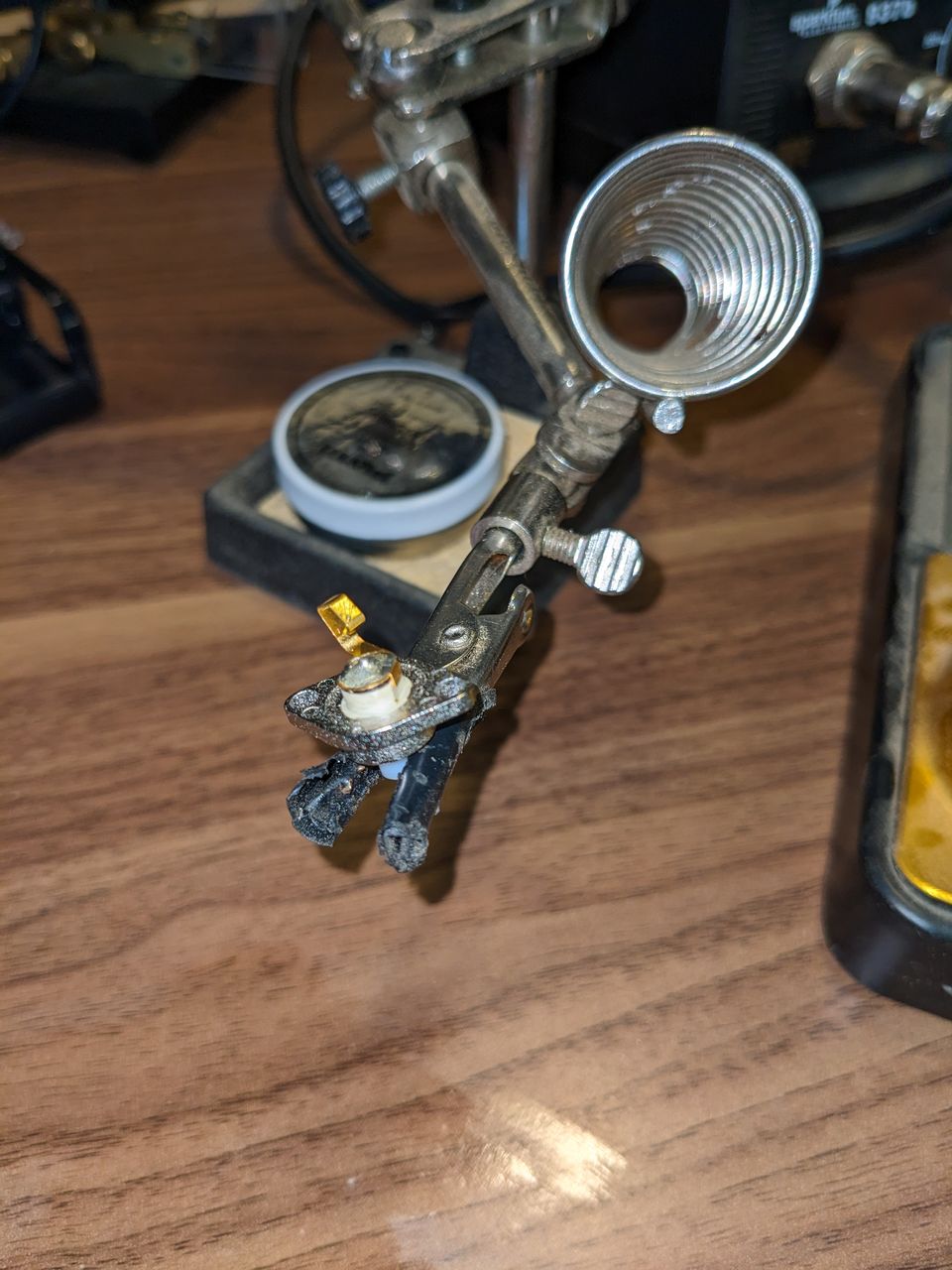
Soldering new connector
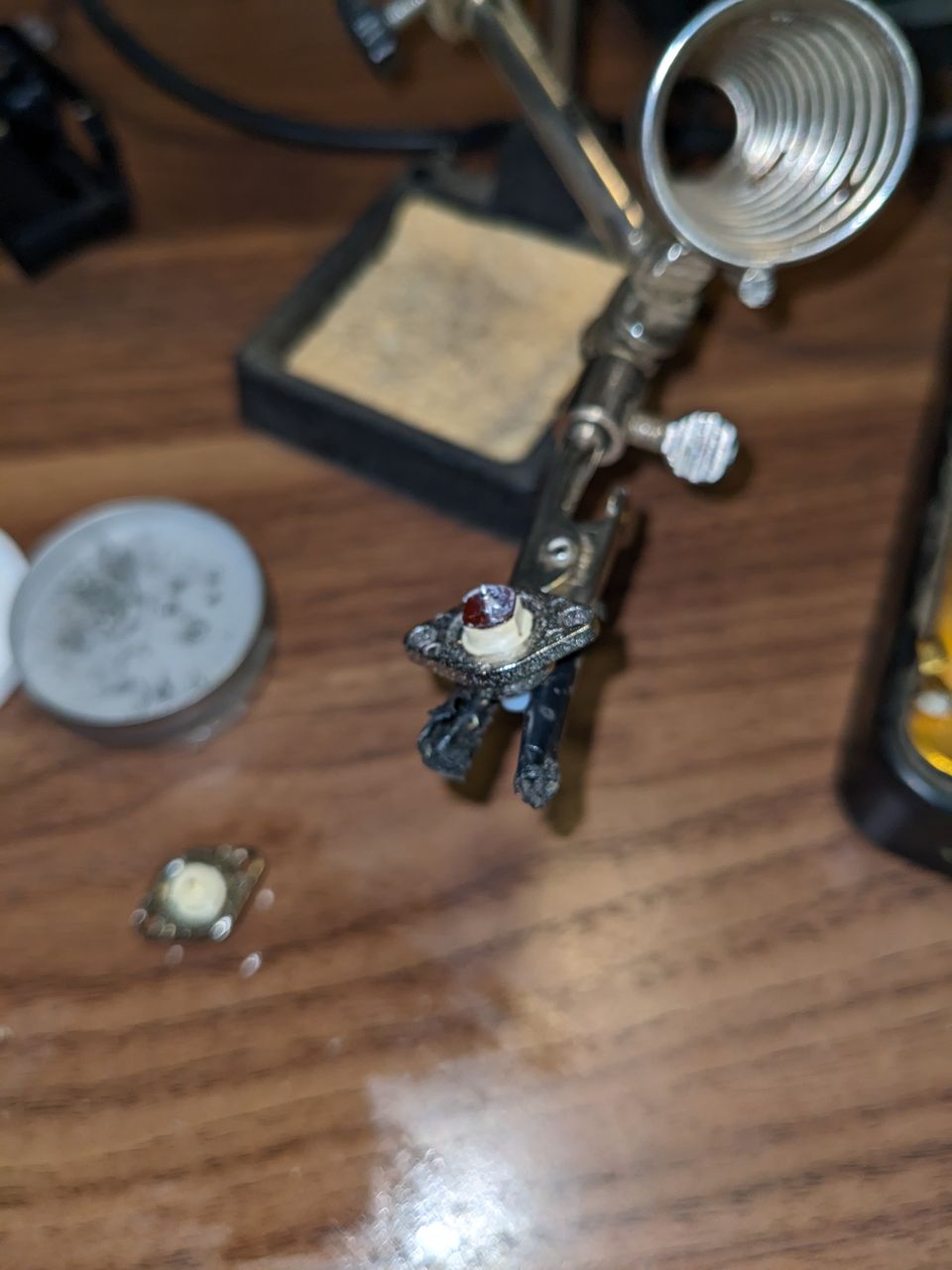
This was the trickiest part for me - thankfully the spring and connector have a couple of flat spots that ensure you align the spring correctly. There is a little red-brown plastic pad (blurry second photo below) between the connector and spring that you need to transfer over before soldering the spring on the new connector. I pried it off with a screwdriver after unsoldering the spring, which took a little effort. It appeared to have some kind of loose glue holding it.
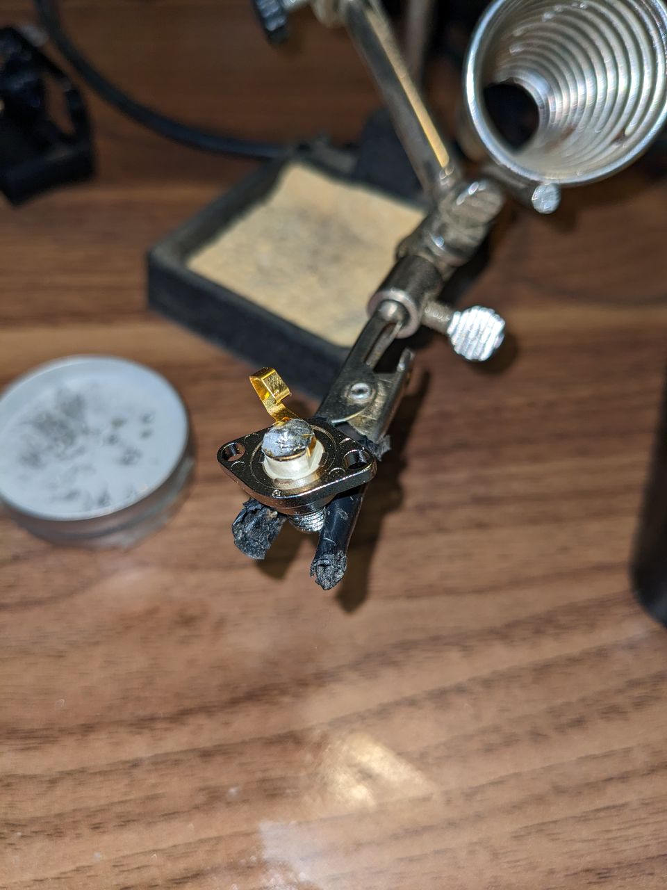
Installing and fixing
Putting it back together is roughly the reverse of disassembly. Once the new connector was installed, I put it all back together and tested on my local repeater. I hadn't gotten a call back but I was at least able to key it up from my basement, which makes me think I sufficiently repaired the radio.
Aug 28, 2022
Purpose
I bought a DDS-60 VFO board from Midnight Design Solutions almost a decade ago, with the intent of using it to build a HF antenna analyzer. I built an Arduino shield to hold it, but never got around to the RF power meters required to use it as an antenna analyzer.
In the summer of 2020, during wildfire season and sociall distancing due to COVID, I was assembling a KD1JV Tri-Bander CW tranceiver kit that a neighbor had bought and not finished. I am not sure that the upper and lower band filters were working correctly, as the radio was totally deaf and putting out zero power. I briefly got out the Arduino DDS-60 sheild that I had built to help diagnose the issue, and wrote a control program to switch between bands.
Details
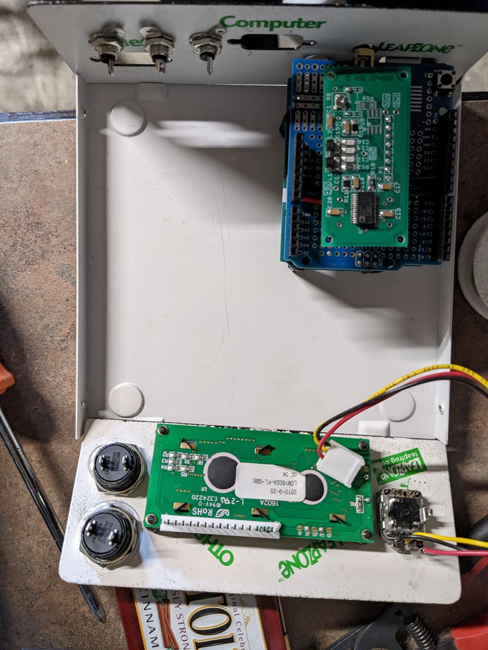
The front panel has room for two buttons, a rotary encoder with a push button built in, and the display. The two buttons and push button on the rotary encoder. On the rear panel, the Arduino's USB port and power supply are available, along with three of the analog pins broken out with RCA connectors for future use.
I designed four modes for the device, selectable by using one of the push buttons.
- Signal Generator: Produces a output at a single frequency.
- Sweep: Sweeps across a range of frequencies automatically.
- VFO: same as signal generator mode, but limited to ham bands, with a button to jump between bands.
- Memory: recalls specific frequencies from the EEPROM. These can be saved via a serial protocol (untested).
The rotary encoder changes the frequency, or the start for the sweep mode. Pressing the button on the rotary encoder changes the step size when the encoder is turned.
The second push button can provide an additional function for each mode. In VFO mode, it switches bands, while in signal generator mode, it increments the frequency by 1 MHz.
Current State
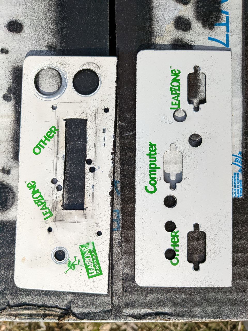
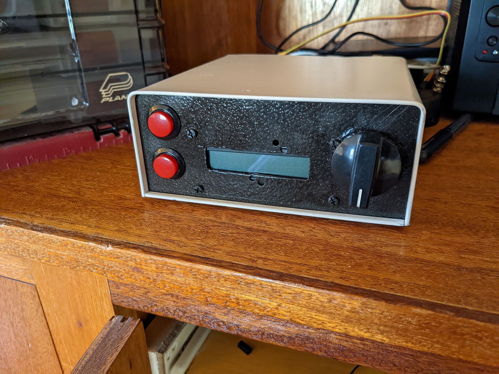
A couple of months ago, my ham neighbor who gave me the tranceiver kit was also clearing out his shack and gave me a number of items, including an old serial port switch that was just the right size to turn into a case. This box came with front and back panels that could be removed entirely from the case, making them particularly easy to work with, and I initially had planned to just flip them around to hide the text. I manually laid out the panels by tracing the panels on a sheet of paper and then trying to trace the components in their locations, trying to reuse or expand existing holes where possible.
The holes I drilled are sloppy, as I am not much of a machinist, but they'll work for this. Particularly cutting out the square hole for the screen was difficult, using a dremel tool cut-off blade to quite a while. After drilling, I took a light grinding bit and buffing bit to clean up any sharp edges.
I spray-painted the panels a black paint that I had sitting around, unfortunately, it beads up to create a hammered metal look, and that resulted in a splotchy looking finish. Maybe not the best look for this panel, but it's the paint I had on hand and was better than the scratched up white paint from my amateur machining.
Before adding leads to the components, I test fit it all in the case. At this point, I managed to mess up the finish a tiny bit by needing to drill an additional hole for the pin that keeps the rotary encoder in place.
August 2022 Update:
I took this project back off the shelf to work on the software and rewired some of the interface elements. After burning out the first display I had planned to use, I had decided to try a standard 16x2 LCD display. I found a couple in a box of parts my neighbor gave me, and ended up ordering an I2C for it from Jameco to make the wiring a bit easier. I seem to have incorrectly wired the rotary encoder as it will only register increasing values - after trying three different Arduino libraries, I realized it must be a hardware thing, I am pretty sure I grounded the wrong pin on the rotary encoder. Having the display has helped me test the UI elements.
I've been maintaining a github repo with the sketch, a few design files, and the test sketch.
The code still needs a bit of work - I am doing something wrong with type casting, as soon as you start turning the dial, the display frequency goes haywire. Maybe this is only an issue with me using sprintf, but I expect it is deeper than that. Once I have the rotary encoder fixed, this'll be the next thing I address.
Jun 20, 2022
(This post is very much a work-in-progress when posted, and I mostly wrote up from my notes on configuring the box)
I've been wanting to set up a couple of projects that would be best served by something like a Raspberry Pi - lightweight processes that are always on. Unfortunately, they're impossible to find. I had been considering replacing my TV computer (really my spouse's old laptop) with an Android/Chromecast device, and after a little research I found a review of one sold by Walmart for $20. That lead me to the question every nerd should ask when they see a device that cheap... does it run Linux? I didn't find an answer to that question, but I found many similar generic Android TV boxes for sale on various websites. Surely those run Linux, and of course they do.
(Side note: I've variously tried to run my ham projects on WSL and not had much luck on my old Windows 10 machine. Remote GUI was a pain, and Linux audio is always a difficulty. So back to a dedicated Linux box.)
There are a variety of these, powered by a number of SoC processors, but the Amlogic S9xx series seems well supported by the Armbian project, and readily available. (Note: After ordering this board, I found some concerns about Armbian's practices.)
After searching for various devices and comparing specifications with prices, I decided to buy one for around $30 that included 64GB eMMC storage and 4GB RAM, but only 100M ethernet. For $30, this should be sufficient for my ham shack machine, and maybe enough to run a few other services. Following their instructions, and these extra steps to configure booting.
Boot configuration
My model wasn't specifically listed (Sunisery H96 Max, says s905x2 CPU with 4G RAM), a similar sounding "X96 MAX" was available, so I ended up trying this dtb file: meson-g12a-x96-max.dtb. It seems to work. When trying to reboot the TV box into linux, don't forget to hit the reset button (inside the AV port) to enable multiboot.
Next Steps
Now that I have Linux booting on this device, I can work towards the following
- WSJT-X configuration with SDR for 6m/VHF reception
- Shack Control box to remotely turn on radio and run remote antenna switch.
- APRS iGate with KISS TNC, GPS module, old 2m radio?
Concerns
- Ethernet not functional: Have not investigated this one yet.
- Unable to change passwords: Solution - I just needed to use
sudo passwd from my account.
- Long term support of Armbian?: Armbian states that their mission is to extend support for these unsupported ARM SoCs, which I greatly appreciate. I feel like I've been burned on dev boards going out of support before, so I'm still a little worried.
- Power draw from small power supply: Plugging in my Griffin iMic USB sound card works fine. A beefier USB sound card (with RCA inputs and several more channels) appeared to draw too much power. I have a powered USB 2.0 hub that I should test it with.
Apr 17, 2022
I have been trying to run my ham radio programs in WSL lately. I've poked around with WSL in the past to run a media servers, but never looked into it much in regards to hardware or porgrams with a GUI. Unfortunately, I haven't found a good SDR receiver software for Windows that will interface via audio with "soundcard" mode software, such as the WSJT-X.
So, I'm running my shack on an old (circa 2010-2012) gaming desktop that is stuck on Windows 10. I'd still like to play games on it, and I currently use the Windows side as a fileserver for backups. As a result, I don't want to boot into Linux just to keep a ham receiver running overnight.
Of course, an easier answer would be put move all this to a remote linux box running on a lower powered SBC. The downsides to that are that it costs money (and boy are Raspberry Pis expensive these days), and it's one more device to administer, whereas this experimentation only costs time.
I figure I'll need to make the following WSL features work to use it for ham radio:
I've tested these on my Windows 11 tablet, where I'm now stuck on SoapySDR/CubicSDR finding the RTLSDR receiver but not appearing to actually pull data from it. Now I need to try these steps again on my Windows 10 desktop. I'm stuck on the GUI working from there, I think I need to experiment with X Forwarding next.
Once I have those features working, I plan on testing WSJT-X and CubicSDR (which relies on SoapySDR).
Feb 05, 2022
Motivation
I've been trying to operate my HF radio station remotely for the last month, using Windows Remote Desktop and WSJT-X to sit and make some FT8 contacts while drinking my morning coffee. This has worked well but I want to remove the step of having to remember to turn off my radio when I am done. The power supply and radio are mounted in a closed cabinet. Leaving the cabinet open invites exploration by our feline companion, while leaving it shut and powered up for long periods of time may result in the temperature rising more than I want.
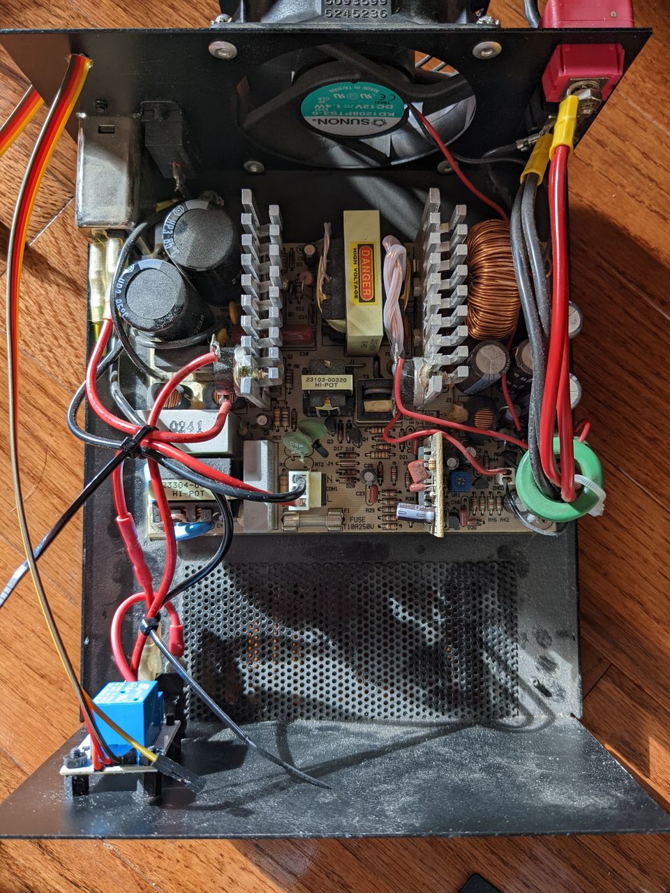
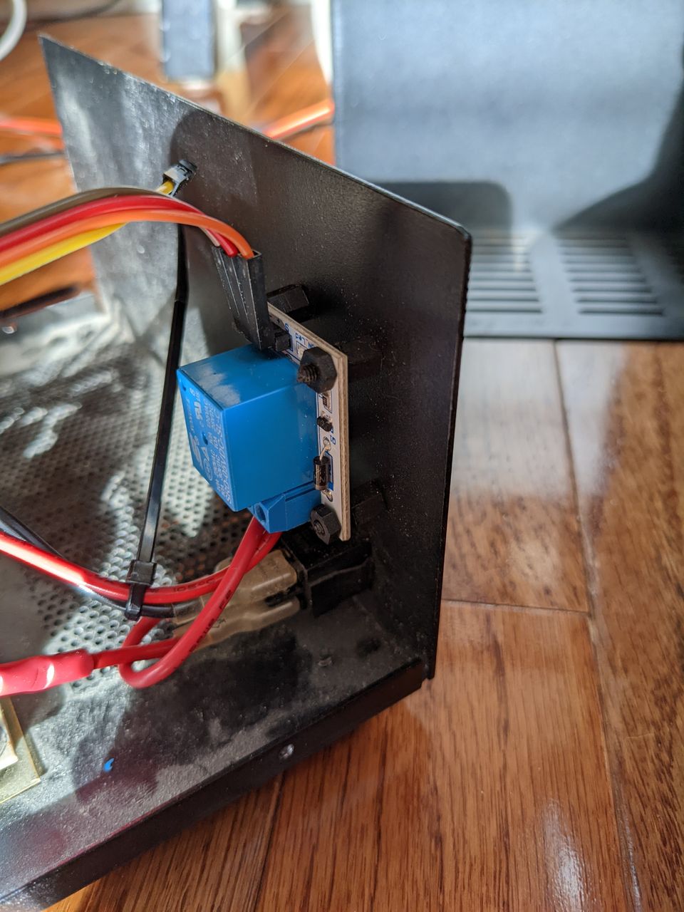
I ordered a simple relay board and decided to put it inside of my power supply, to be triggered by a program on the computer to turn the station on and off. West Mountain Radio sells a network connected control and monitor system with Power Pole connectors that would be great for this, but it's also $280 which is a lot more than I want to spend for this little effort.
Progress
Last weekend after getting all the parts, I took a few moments out in my shop to drill out some holes and mount the relay board, and wire the relay into the circuit of the power supply. I had selected a relay that is adequate for the AC side of the power supply, which are more commonly available on a premade board than those capable of handling 12V/25A. I made a few mistakes wiring it up, first mistakenly wiring it in series with the light inside the switch, and then wiring it to be normally closed when the relay is not powered.
 .
.
 .
.
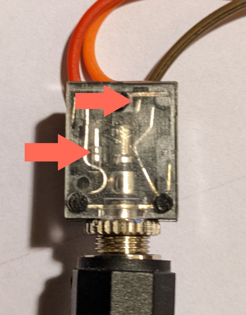
The final mistake I made was wiring up connector that I put on the back of my power supply. I had decided to use a 1/8" TRS connector to provide power, ground, and signal to the relay from the control board, but instead of soldering to the tip and ring pins, I soldered to pins used to indicate when the plug is removed! I connected ground to the shield, power to the ring, and signal to the tip, figuring this would ensure the least bad results if any of the pins made contact while inserting the plug.
After fixing the misconnected pins on the TRS socket, I needed to wire this up to my computer somehow. My temporary solution is to use an old Arduino (which has been flaky to program) to provide +5V and ground to power the relay whenever my computer is connected to it. Longer term, I am planning to develop a shack control board and software that can use an Arduino or similar board to monitor and control several aspects of my shack.
Jan 21, 2022
My home shack (circa-2015 to early 2023):
(add recent photo here)
Installed in a built-in cabinet in my living room is a small shack that I use for HF work.
- Icom IC-706 MkIIG
- LDG Z-series auto tuner
- MFJ manual tuner, used for SWR meter and switch.
- West Mountain Radio Rig Blaster P&P
- USB Sound Card
- Astron switching power supply
Antennas:
- Half-size G5RV for HF/6M, currently at around 18 ft off the ground.
Future improvements:
- Install 2-element 6m antenna on rotator on a mast over my garage.
- 2m and 70cm
Dec 11, 2021
Design
I wanted a remote antenna switch, and commercial models seem to be expensive relative to what I am willing to spend. I planned to combine an Arduino, ethernet shield with power over ethernet, and a board with four relays. This assumes that commonly available relay boards would work fine for switching HF signals, providing both adequate isolation (separation when an antenna is turned off) and have minimal losses when in use. I had planned to add on remote control for an automatic antenna tuner and an antenna rotator, but those two features will be for some future iteration of the project. I have at least two HF antennas I wanted to connect, a short G5RV and a two element 6M beam.
Micrcontroller
After running into issues with a standard Arduino Uno and ethernet shield - there wasn't enough memory to serve up a minimal HTML page via HTTP to control the switch. I looked at some successful projects using networked Arduinos for remote control, like the OpenSprinkler, finding the source code was more optimized than I thought I could get for a one-off hobby project.
Next idea was to look at something like the Arduino Yún, which I discovered was unavailable at tthe time. I did find Adafruit selling a clone called the Seeeduino Cloud, marked as compatible with the Yún, and bought a Power over Ethernet (POE). I would not recommend the Seeeduino Cloud as it uses a custom branch of the OpenWRT Linux distribution that several years since having any kind of update, and minimal documentation. So I set up two parts - a static HTML page with JavaScript for interactivity, served up by the Seeeduino's Linux side, and used the Arduino YunBridge library with a REST API to turn the appropriate pins for each relay on and off. It works okay, but can be a bit buggy when the Arduino loses it's connection.
Relay board
I mounted a Sainsmart relay board and Seeeduino into an old project box I had bought years ago for a manual antenna switch and never implemented. I built a small RF sheild around the relay board using an old piece of aluminum bent to fit around it, and wired it up using some speaker wire and panel mount SO239 connectors
I had considered their relay board with a built-in web server, but this was out of stock at the time.
Testing
I can't tell if there is any isolation between these. I used a friend's NanoVNA to find minimal losses on each of the connectors when selected, but I cannot hear any difference between connectors on the radio with one antenna hooked up.
My next steps will be to rewire the relay board to directly solder to the PCB with short stubs of 14 gage copper wire to each connector and see if this works better.
Antenna Rotator?
My neighbor, another ham, gave me a TV antenna rotator and homebrew controller. The controller requires a five wire connection to the rotator, three for power and two to measure voltage across a potentiometer that indicates direction. I had planned to incorporate controlling the rotator into the initial project until I started to investiate how to provide power to it. The antenna rotator obviously requires more power to operate than I could deliver over PoE. The homebrew controller provides 40V AC from a substanial transformer connected 110V AC. The 40V AC appears to need to be reversed to rotate the controller in opposite directions, meaning four relays need to be used as a DPDT switch. By the time I configure this, I still need to provide at least three wires up to the rotator, plus the ethernet to the Seeeduino. I am not sure I'll complete this, instead I am planning to run 18 gauge, 7 conductor, sprinkler wire to the rotator.
Antenna Tuner?
Secondary to the antenna switch and rotator controller, I wanted to connect either my LDG Z100 autotuner or another autotuner to the Seeeduino. Locating the tuner near the antenna switch would allow me to minimize the impedance mismatch over the majority of my feedline, about 50ft from my shack to the mast on my garage. The controls for the LDG autotuner appear to be pretty minimal, using a four pin connector from my Icom radio, esentially power and ground, and two pins communicate when to tune and status of tuning. This should be easy to add at a future point.
Dec 09, 2021
Plans
One of those magical things that has kept me interested in ham radio all these years has been the idea of bouncing signals off of things, particularly those in space. I've long wanted to give meteor scatter a try, so I want to get my station set up for that this winter. It seems much more within reach than satellite operations (next on my list) or EME communication. Satellite repeaters requiring specialized antennas or at least good timing and knowing where to point a handheld antenna, while EME requiring some amplifiers outside of my budget for this hobby.
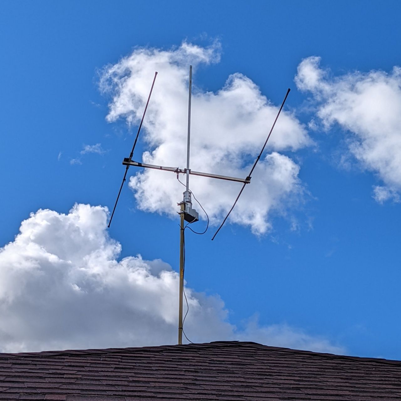
It appears I can use a 2-element beam for 50MHz that my neighbor gave me, along with my IC-706MKIIG radio, and the WSJT-X software. I want to mount the 50MHz antenna on a mast over my garage, and then get the software and radio set up to try some meteor scatter contacts in the morning before my kid gets up.
A few resources I've been refering to.
The pages I've looked at to help me assemble this station:
Progress - February 2022
I got my 6m antenna up this weekend on a tripod and 10 foot mast. This is at the high end of the recommended height without guywires for the tripod, so I should make adding those my next step. I've been unable to get a friend's NanoVNA to work to check the antenna's resonance.
I gave up on trying to automate the rotator, I might add something to the control box in the future, but for now, the antenna is facing roughly southeast, which I hope will give me some opportunity for early morning meteor scatter operations.
Nov 13, 2021
Woodworking
Ongoing:
Completed:
Someday:
- Solid wood base for a custom record player
- New legs for my desk
Ham Radio
Ongoing:
Someday:
Computers/Programming
Ongoing:
Completed:
Python
R
Someday:
- Email migration from gmail