DDS-60 Signal Generator and VFO
Purpose
I bought a DDS-60 VFO board from Midnight Design Solutions almost a decade ago, with the intent of using it to build a HF antenna analyzer. I built an Arduino shield to hold it, but never got around to the RF power meters required to use it as an antenna analyzer.
In the summer of 2020, during wildfire season and sociall distancing due to COVID, I was assembling a KD1JV Tri-Bander CW tranceiver kit that a neighbor had bought and not finished. I am not sure that the upper and lower band filters were working correctly, as the radio was totally deaf and putting out zero power. I briefly got out the Arduino DDS-60 sheild that I had built to help diagnose the issue, and wrote a control program to switch between bands.
Details
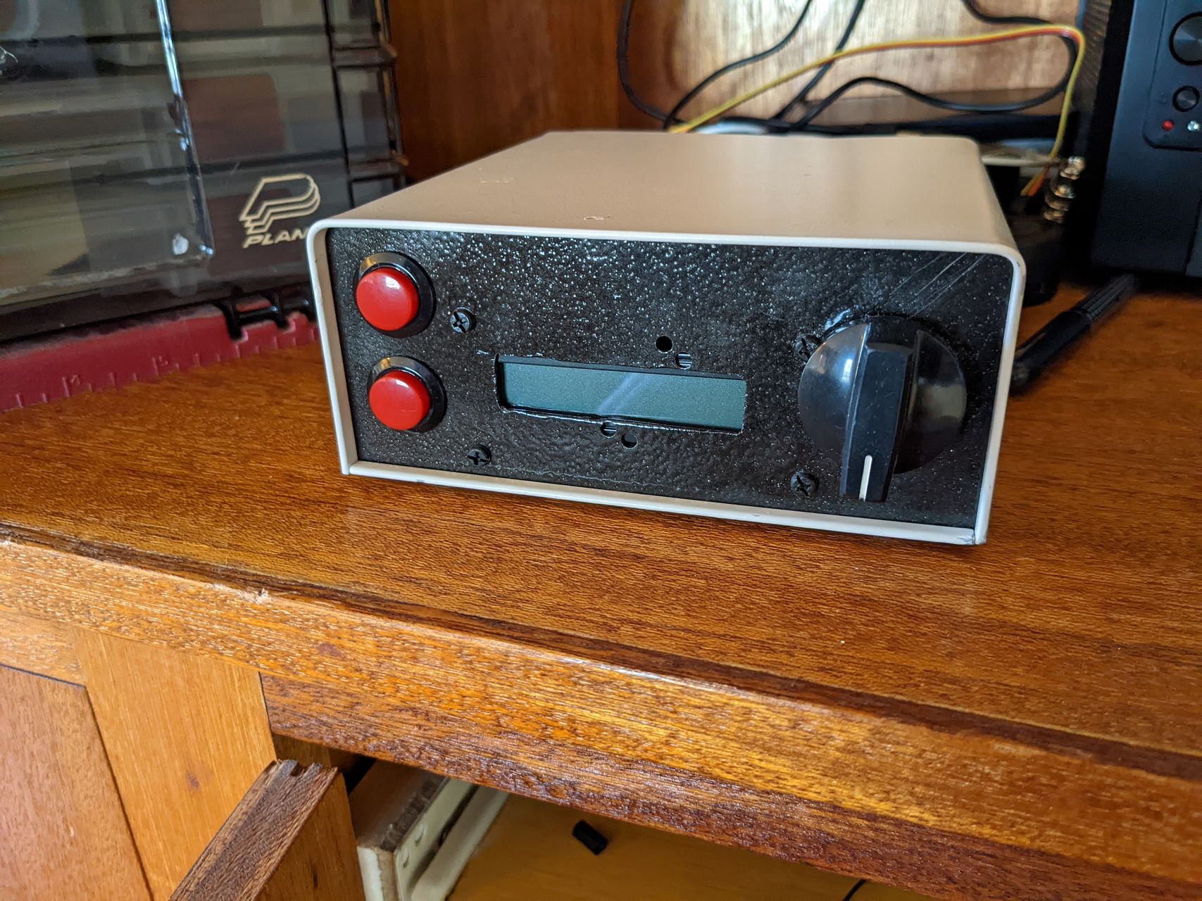
The front panel has room for two buttons, a rotary encoder with a push button built in, and the display. The two buttons and push button on the rotary encoder. On the rear panel, the Arduino's USB port and power supply are available, along with three of the analog pins broken out with RCA connectors for future use.
I designed four modes for the device, selectable by using one of the push buttons.
- Signal Generator: Produces a output at a single frequency.
- Sweep: Sweeps across a range of frequencies automatically.
- VFO: same as signal generator mode, but limited to ham bands, with a button to jump between bands.
- Memory: recalls specific frequencies from the EEPROM. These can be saved via a serial protocol (untested).
The rotary encoder changes the frequency, or the start for the sweep mode. Pressing the button on the rotary encoder changes the step size when the encoder is turned.
The second push button can provide an additional function for each mode. In VFO mode, it switches bands, while in signal generator mode, it increments the frequency by 1 MHz.
Current State
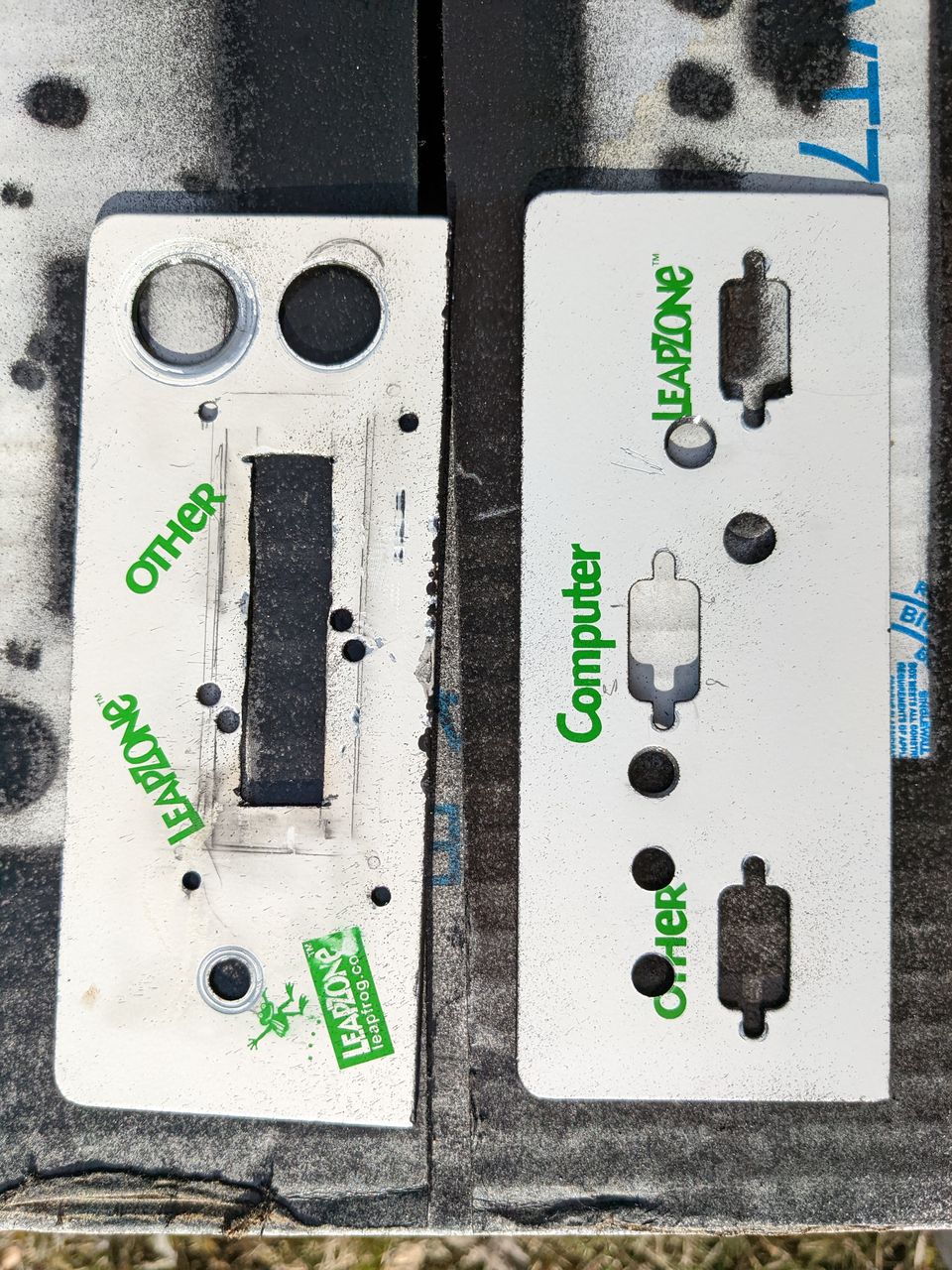
A couple of months ago, my ham neighbor who gave me the tranceiver kit was also clearing out his shack and gave me a number of items, including an old serial port switch that was just the right size to turn into a case. This box came with front and back panels that could be removed entirely from the case, making them particularly easy to work with, and I initially had planned to just flip them around to hide the text. I manually laid out the panels by tracing the panels on a sheet of paper and then trying to trace the components in their locations, trying to reuse or expand existing holes where possible.
The holes I drilled are sloppy, as I am not much of a machinist, but they'll work for this. Particularly cutting out the square hole for the screen was difficult, using a dremel tool cut-off blade to quite a while. After drilling, I took a light grinding bit and buffing bit to clean up any sharp edges.
I spray-painted the panels a black paint that I had sitting around, unfortunately, it beads up to create a hammered metal look, and that resulted in a splotchy looking finish. Maybe not the best look for this panel, but it's the paint I had on hand and was better than the scratched up white paint from my amateur machining.
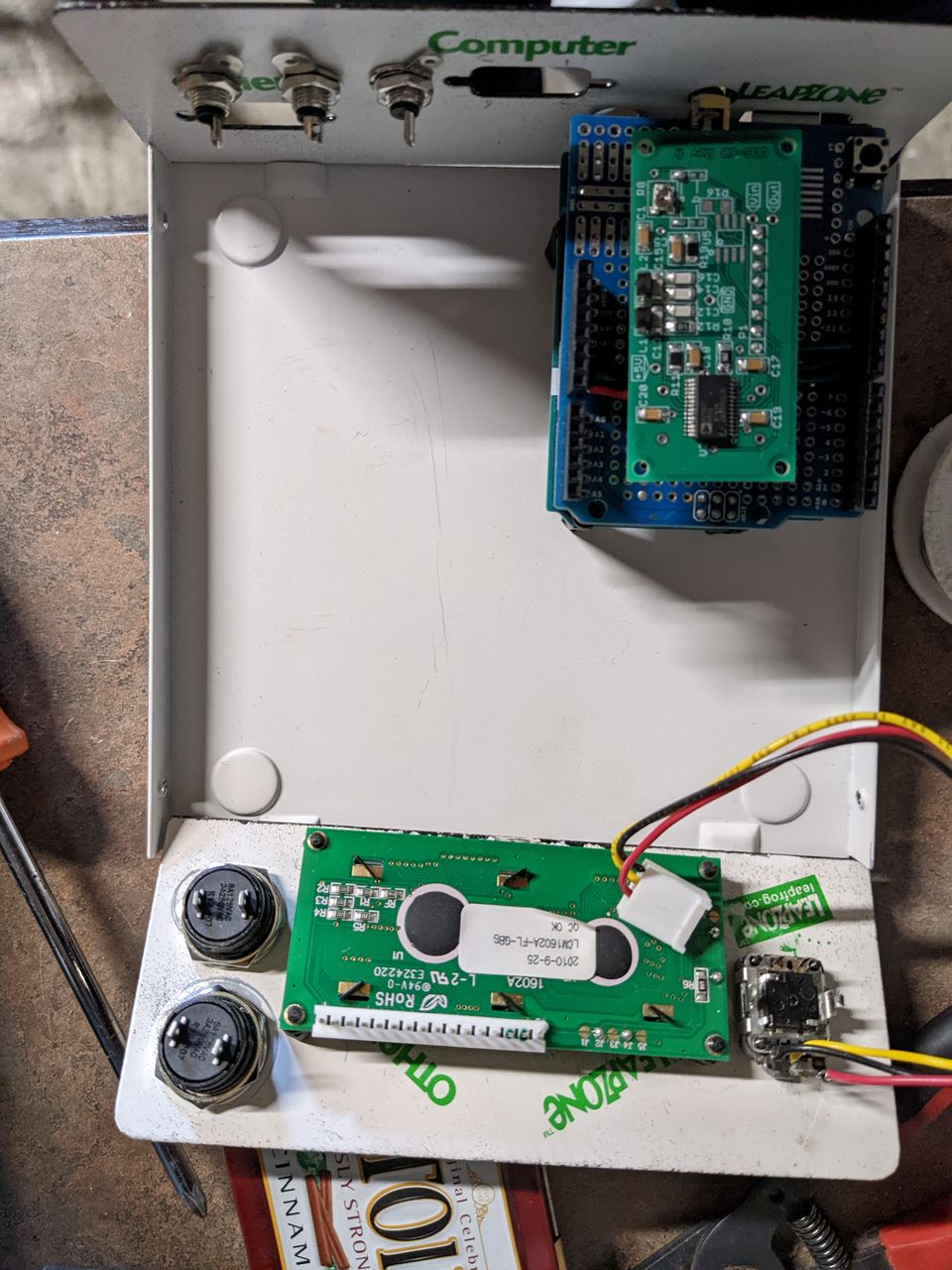
Before adding leads to the components, I test fit it all in the case. At this point, I managed to mess up the finish a tiny bit by needing to drill an additional hole for the pin that keeps the rotary encoder in place.
August 2022 Update:
I took this project back off the shelf to work on the software and rewired some of the interface elements. After burning out the first display I had planned to use, I had decided to try a standard 16x2 LCD display. I found a couple in a box of parts my neighbor gave me, and ended up ordering an I2C for it from Jameco to make the wiring a bit easier. I seem to have incorrectly wired the rotary encoder as it will only register increasing values - after trying three different Arduino libraries, I realized it must be a hardware thing, I am pretty sure I grounded the wrong pin on the rotary encoder. Having the display has helped me test the UI elements.
I've been maintaining a github repo with the sketch, a few design files, and the test sketch.
The code still needs a bit of work - I am doing something wrong with type casting, as soon as you start turning the dial, the display frequency goes haywire. Maybe this is only an issue with me using sprintf, but I expect it is deeper than that. Once I have the rotary encoder fixed, this'll be the next thing I address.